SKIP TO CONTENT

Trim Seperator

Trim Separator Diagram

Our Locations

Inlet.
Adjustable Vane.
Access doors on both sides for cleaning and removing separation screens.
Trim Outlet.

Perforated Plate Separation Screens

  • Designed to withstand impact from log saw cookies.
  • Stronger than competitive designs using wire cloth screens.
Air Outlet to Dust Collection.
  • Inlet.
  • Adjustable Vane.
  • Access doors on both sides for cleaning and removing separation screens.
  • Trim Outlet.
  • Perforated Plate Separation Screens
    (a)Designed to withstand impact from log saw cookies.
    (b)Stronger than competitive designs using wire cloth screens.
  • Air Outlet to Dust Collection.

Self-Cleaning Paper Trap

Our patented, Self-Cleaning Paper trap captures tissue broke collected at our dust capture hoods and floor sweeps preventing the broke from plugging downstream dust collectors.

Our Locations

Trap Media – Any broke that is drawn into the Dust Capture Hoods is captured on the trap. A pressure switch activates cleaning cycle upon significant broke buildup on trap.

Exhaust Bypass Damper – The Exhaust Bypass Damper switches to bypass mode to stop air flow through trap.

Trapdoor – The trapdoor opens and the accumulated broke drops out by gravity. Compressed air jets dislodge any broke that is hung up on the surface of the trap.

  • Trap Media – Any broke that is drawn into the Dust Capture Hoods is captured on the trap. A pressure switch activates cleaning cycle upon significant broke buildup on trap.
  • Exhaust Bypass Damper – The Exhaust Bypass Damper switches to bypass mode to stop air flow through trap.
  • Trapdoor – The trapdoor opens and the accumulated broke drops out by gravity. Compressed air jets dislodge any broke that is hung up on the surface of the trap.

Floor Sweeps

Our floor sweep systems reduce operator and machine down time required for converting line blow downs.

  • Allows for quick removal of accumulations on workroom floor.
  • Reduces downtime for greater efficiency

Floor Sweep

Our Locations

Center or end exhaust connections available.

Vortex-generating header.

Floor serves as bottom side of header.

Optional pins to prevent large debris from entering floor sweep.

  • Center or end exhaust connections available.
  • Vortex-generating header.
  • Floor serves as bottom side of header.
  • Optional pins to prevent large debris from entering floor sweep.

Floor Sweep System

Our Locations

Floor Sweep – Collects dust.

Vortex-generating header prevents dust buildup.

Sweep Nozzle – Sweeps dust towards the floor sweep. Uses low pressure air from a pressure blower rather than compressed air to reduce operating cost.

Sweep nozzle is designed to aspirate air from entering side of nozzle. This enables us to install several nozzles in series to sweep longer distances.

  • Floor Sweep – Collects dust.
  • Vortex-generating header prevents dust buildup.
  • Sweep Nozzle – Sweeps dust towards the floor sweep. Uses low pressure air from a pressure blower rather than compressed air to reduce operating cost.
  • Sweep nozzle is designed to aspirate air from entering side of nozzle. This enables us to install several nozzles in series to sweep longer distances.

Web Cleaner

Our Web Cleaner removes loose fibers from the surface of the web walls using a web stabilizing jet of high velocity air.

  • Reduces consumer product dust complaints and improves overall air quality
  • Reduces dust accumulation and maintenance at printers, adhesive applicator rolls and adhesive ply bonders
Our Locations

Directs a high velocity jet of air parallel to and in the same direction as web travel. This high velocity jet removes loose fibers without causing sheet disturbances

Exhaust Header – Captures dust removed by the high velocity air jet. Vortex generating design prevents dust buildup inside header.

  • Supply Nozzle – Directs a high velocity jet of air parallel to and in the same direction as web travel. This high velocity jet removes loose fibers without causing sheet disturbances.
  • Exhaust Header – Captures dust removed by the high velocity air jet.
    Vortex generating design prevents dust buildup inside header.

Dust Capture Hoods

Our Vortex-Generating Dust Capture Hoods are the “heart” of our Dust Collection Systems.

  • Vortex-Generating design prevents dust buildup inside exhaust header minimizing fire hazard
  • Dust capture hoods can handle large pieces of broke and even full width sheet without plugging
  • No “broke catchers” on our exhaust slots that need to be cleaned

Dust Capture Hood Process Diagram

Our Locations

Vortex generating header prevents dust buildup, minimizing fire hazard.

Header design provides uniform cross-machine exhaust flow without a tapered exhaust slot.

Throat design minimizes plugging, it can handle large pieces of broke and full width sheet without plugging. No “broke catchers” that need to be cleaned.

  • Vortex generating header prevents dust buildup, minimizing fire hazard.
  • Header design provides uniform cross-machine exhaust flow without a tapered exhaust slot.
  • Throat design minimizes plugging, it can handle large pieces of broke and full width sheet without plugging. No “broke catchers” that need to be cleaned.

Recuperative Thermal Oxidizers

Recuperative Thermal Oxidizers, sometimes referred to as afterburners, utilize direct combustion to convert volatile organic compounds in gaseous effluents to carbon dioxide and water with maximum effectiveness. The heat discharged from the oxidizer can frequently be recovered, reducing the overall cost of afterburner operation. Heat recovery methods may include using heat exchangers to preheat the contaminated gasses prior to entry into the oxidizer, using heat exchangers to preheat combustion air, and using the waste heat for process equipment such as boilers or ovens. EnviroAir custom designs each system, considering such important design principles as proper combustion chamber mixing, sufficiently high temperatures, and adequate time for the combustion process. Additionally, the orientation of the oxidizer can be changed to suit the customer’s space constraints.

EnviroAir Recuperative Thermal Oxidizers Feature:

  • Automatic operation – lowers costs
  • Solid body construction – for durability
  • Fully enclosed heating unit – safer to operate
  • Achieves maximum effectiveness – fulfills all EPA regulations for clean air standards

Typical Operation of Recuperative Thermal Oxidizers

Heat Exchanger
The forced draft fan draws in process air and discharges it to the heat exchanger. The process air is preheated in the heat exchanger to raise the temperature closer to the required destruction temperature. The thermal oxidizer then continues heating the process air to the design set point temperature utilizing the burner.

Recuperative thermal oxidizer used in VOC destruction.
Turbulence is created as the air passes by the burner and into the combustion chamber to ensure proper mixing. The combustion chamber is sized to provide the residence time required to destroy the hydrocarbons in the air. The clean hot air then passes back through the heat exchanger to preheat the incoming air. The clean air then leaves the heat exchanger and flows up the stack to atmosphere.

Direct fired thermal oxidizers

Direct thermal oxidizers, sometimes referred to as afterburners, utilize direct combustion to convert volatile organic compounds in gaseous effluents to carbon dioxide and water with maximum effectiveness. The clean air can then be discharged safely into the atmosphere.  EnviroAir custom designs each system, considering such important design principles as proper combustion chamber mixing, sufficiently high temperatures, and adequate time for the combustion process. Additionally, the orientation of the oxidizer can be changed to suit the customers space constraints.

EnviroAir Direct Thermal Oxidizers Feature:

  • Automatic operation – lowers costs
  • Solid body construction – for durability
  • Fully enclosed heating unit – safer to operate
  • Achieves maximum effectiveness – fulfills all EPA regulations for clean air standards

Typical Operation of Thermal Oxidizers

The forced draft fan draws in process air and discharges it to the thermal oxidizer. In the thermal oxidizer, the process air is heated to the design set point temperature by the burner. Turbulence is created as the air passes by the burner and into the combustion chamber to ensure proper mixing. The combustion chamber is sized to provide the residence time required to destroy the hydrocarbons in the air. The clean hot air then flows up the stack to the atmosphere.

Packed bed scrubbers

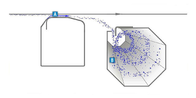
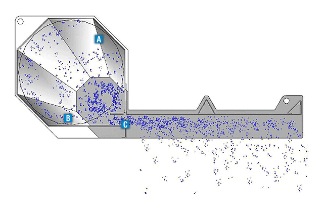
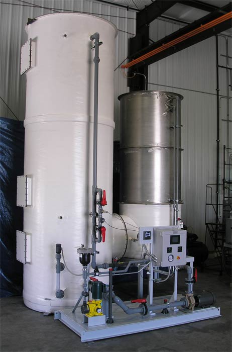
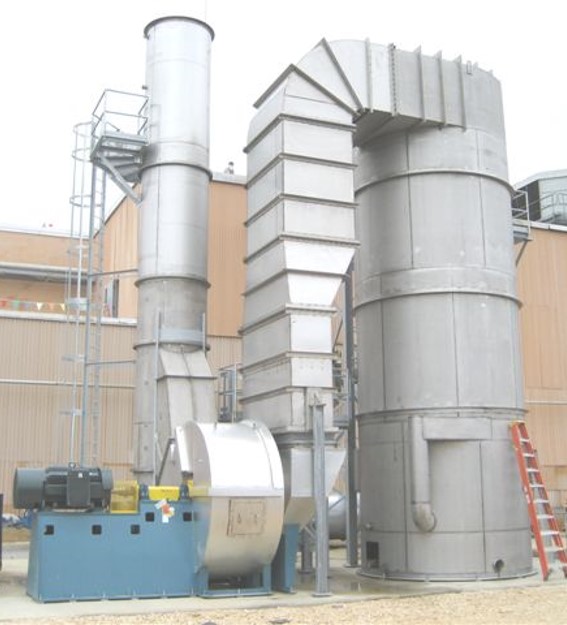
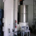
EnviroAir designs custom wet scrubber systems including packed bed scrubbers. Our specialty is turnkey installations of environmental air systems and can provide single source responsibility for the design, fabrication, installation and startup of your wet scrubber system. Packed towers or packed bed scrubbers are essentially contact beds through which gases and liquid pass counter currently or cross flow. They are used primarily for applications involving extreme pH gases, odors, vapors, and mist removal. While these collectors can capture solids, they are not normally used for this purpose because wet dust collecting in the beds would require unreasonable maintenance.

Packed bed scrubbers are designed to neutralize gases and odors produced during manufacturing processes. Usually, the flow through a packed bed scrubber is counter current, the liquid is introduced at the top and flows down through the packing, while gas is introduced at the bottom to flow upward through the packing. The packing is designed to produce a large surface area for the liquid to contact the solute gas. The countercurrent flow is highly efficient since, as the concentration of pollutant in the gas decreases while rising through the tower, there is a constantly fresher neutralization liquid available for contact.

Optional Packages

EnviroAir utilizes pH controls, flow meters, ORP controls, and conductivity controls to provide a system with highly efficient gas treatment and maximum user flexibility. Often, a simple change of feed chemical is all that is needed to accommodate a change in process gas. Optional packages include high temperature quench sections, multiple stage designs, and horizontal profile scrubbers.

Venturi scrubbers

EnviroAir can provide a venturi scrubber to remove dust from the exhaust air. Our venturi scrubber has a wetted wall venturi eliminating both the wet/dry interface region where buildup often occurs, and the atomizing spray nozzles that are susceptible to plugging. The dust-laden air and water are accelerated in the converging section of the venturi. The water is atomized in the venturi throat and the dust particles collide with and are absorbed by the water droplets.

In a normal profile scrubber, the exhaust air and dust-laden water droplets enter a cyclonic separator through a tangential inlet. The tangential inlet causes the flow to spin through the separator towards the top discharge. The heavy dust-laden water droplets are thrown to the separator wall by centrifugal force where they collect and coalesce. This liquid slurry runs down the separator wall to the bottom drain or integral recirculation tank. The clean exhaust air is discharged out the top of the separator.

Advantages Compared to Wet Scrubbers:

  • Cleaned air is returned to machine room reducing winter heating costs
  • Lower pressure drop resulting in lower fan horsepower


Advantages Compared to Baghouses:

  • Simple design – easy to understand and maintain
  • Reduced fire and explosion hazard – no cloud of dust from bag pulsing


Advantages Compared to Conventional Drum Filter Designs:

  • Air passes from the inside to outside of filter drum collecting particulate in the inside of drum preventing dust from collecting on the enclosure floor
  • Stationary drum has no rotary seal prone to wear and leakage
  • More efficient than conventional drum filters results in longer service life for downstream final filters

EnviroAir also offers a low-profile design. Instead of a single cyclonic separator, this design uses multiple cyclonic separators in parallel with a single venturi.  The cyclonic separators drain to a common recirculation tank.

The low profile venturi scrubber pictured is removing dust from 22,000 cfm of air exhausted from a paper machine.

Pilot Test Equipment

Our facility in Southeast Wisconsin includes pilot equipment for developing new products and processes. This pilot equipment is available for customer demonstrations and trials.

Bench Scale Pilot Furnace

Our bench scale pilot unit can be converted to operate in rotary borings dryer mode or rotary retort furnace mode. The small scale allows for economical hardware changes when developing new processes and products. This unit can be used for developing and demonstrating chip drying, chip drying in an inert atmosphere, catalyst reclamation, and biomass torrefaction. The data from these trials is used to determine the proper size of production scale furnaces and dryers.

Production Scale Pilot Furnace

Our production scale pilot rotary retort furnace is capable of processing 1,000 lb/hr of waste foundry sand or 120 lb/hr of spent catalyst or activated carbon. This unit is available for customer trials and demonstrations.